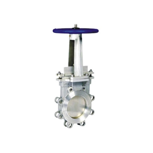
Stop Valve Flow Coefficient and Hydraulic Performance
1. Introduction
Stop valves, also known as isolation valves, are essential components in fluid control systems, widely used in industries such as water supply, oil and gas, chemical processing, and HVAC. Their primary function is to regulate or completely shut off fluid flow in pipelines. The hydraulic performance of stop valves is a critical factor in determining their efficiency, pressure drop, and overall system performance. One of the key parameters used to evaluate this performance is the flow coefficient (Cv or Kv), which quantifies the valve's ability to allow fluid passage under specific conditions.
This paper explores the concept of the flow coefficient, its significance in hydraulic performance, and the factors influencing valve efficiency. Additionally, it discusses testing methods, industry standards, and optimization strategies for improving stop valve performance.
---
2. Understanding the Flow Coefficient (Cv and Kv)
2.1 Definition and Calculation
The flow coefficient (Cv or Kv) is a dimensionless number that indicates the flow capacity of a valve. It represents the volume of water (in gallons per minute, GPM) that passes through a fully open valve at a pressure drop of 1 psi (pound per square inch) at 60°F (15.5°C).
- Cv (Imperial Units):
\[
C_v = Q \sqrt{\frac{SG}{\Delta P}}
\]
Where:
- \( Q \) = Flow rate (GPM)
- \( SG \) = Specific gravity of the fluid (relative to water)
- \( \Delta P \) = Pressure drop across the valve (psi)
- Kv (Metric Units):
\[
K_v = Q \sqrt{\frac{SG}{\Delta P}}
\]
Where:
- \( Q \) = Flow rate (m³/h)
- \( \Delta P \) = Pressure drop (bar)
The conversion between Cv and Kv is:
\[
K_v = 0.865 \times C_v
\]
2.2 Importance of Flow Coefficient
The flow coefficient is crucial for:
- Valve Sizing: Ensures the correct valve is selected for a given flow rate and pressure drop.
- System Efficiency: Helps minimize energy losses due to excessive pressure drops.
- Performance Comparison: Allows engineers to compare different valve designs.
---
3. Hydraulic Performance of Stop Valves
3.1 Pressure Drop and Flow Characteristics
The hydraulic performance of a stop valve is primarily influenced by:
- Pressure Drop (ΔP): The difference in pressure between the inlet and outlet of the valve. Excessive pressure drop can lead to energy inefficiency.
- Flow Regime: Laminar or turbulent flow affects the valve’s performance.
- Valve Type: Globe, gate, ball, and butterfly valves exhibit different flow characteristics.
3.2 Flow vs. Pressure Relationship
The relationship between flow rate and pressure drop is nonlinear and depends on:
- Valve Opening Position: Partially open valves increase resistance and pressure drop.
- Fluid Properties: Viscosity and density impact flow behavior.
- Valve Geometry: Internal design (e.g., sharp edges vs. streamlined passages) affects turbulence.
3.3 Cavitation and Flashing
- Cavitation: Occurs when local pressure drops below the vapor pressure, forming bubbles that collapse and damage valve surfaces.
- Flashing: When downstream pressure remains below vapor pressure, causing permanent vaporization.
Both phenomena reduce valve lifespan and efficiency, making proper material selection and design essential.
---
4. Factors Affecting Flow Coefficient and Hydraulic Performance
4.1 Valve Design and Geometry
- Flow Path: A streamlined flow path reduces turbulence and pressure drop.
- Seat and Disc Configuration: Affects flow restriction and sealing efficiency.
- Port Size: Larger ports generally increase Cv but may reduce shut-off capability.
4.2 Material Selection
- Corrosion Resistance: Critical for chemical and seawater applications.
- Erosion Resistance: Important for high-velocity or abrasive fluids.
4.3 Operating Conditions
- Temperature and Pressure: Extreme conditions affect material strength and flow dynamics.
- Fluid Type: Liquids, gases, and multiphase flows behave differently.
4.4 Installation and Maintenance
- Pipe Alignment: Misalignment increases turbulence.
- Wear and Fouling: Deposits and erosion alter flow characteristics over time.
---
5. Testing and Standards for Flow Coefficient
5.1 Industry Standards
- ANSI/ISA-75.01.01 (IEC 60534-2-1): Standard for flow coefficient testing.
- ISO 5208: Defines leakage classifications for valves.
- API 598: Covers valve inspection and testing.
5.2 Testing Methods
1. Water Flow Test: Measures Cv by flowing water through the valve at controlled pressure drops.
2. Air Flow Test: Used for gas applications.
3. Computational Fluid Dynamics (CFD): Simulates flow behavior before physical testing.
5.3 Interpretation of Results
- A higher Cv indicates better flow capacity but may compromise shut-off tightness.
- Optimal Cv balances flow efficiency with pressure drop and sealing performance.
---
6. Optimization Strategies for Improved Hydraulic Performance
6.1 Design Improvements
- Streamlined Flow Paths: Reduce turbulence and pressure losses.
- Multi-Stage Pressure Reduction: Used in high-pressure applications to prevent cavitation.
- Low-Torque Designs: Improve actuation efficiency.
6.2 Material Enhancements
- Hardened Seats: Improve wear resistance.
- Composite Materials: Reduce weight and corrosion risks.
6.3 Smart Valve Technologies
- Automated Control: Adjusts valve position dynamically for optimal flow.
- Sensors and IoT Integration: Monitors performance in real-time.
---
7. Conclusion
The flow coefficient (Cv/Kv) is a fundamental parameter in evaluating the hydraulic performance of stop valves. Understanding its relationship with pressure drop, flow characteristics, and valve design is essential for selecting and optimizing valves in industrial applications. By considering factors such as material selection, operating conditions, and testing standards, engineers can enhance valve efficiency, reduce energy losses, and extend service life. Future advancements in computational modeling and smart valve technologies will further improve hydraulic performance, ensuring reliable and sustainable fluid control systems.
---
This paper provides a comprehensive overview of stop valve flow coefficients and hydraulic performance, offering insights for engineers, designers, and maintenance professionals in fluid control applications.
Situs web ini menggunakan cookie untuk memastikan Anda mendapatkan pengalaman terbaik di situs web kami.
Komentar
(0)